 हिन्दी
 English
 فارسی
فارسی русский
 العربية
 Melayu
 Indonesia
हम आपकी किस प्रकार सहायता कर सकते हैं
आप किसी भी तरह से हमसे संपर्क कर सकते हैं के लिए सुविधाजनक है आप । हम उपलब्ध हैं 24 / 7 के माध्यम से ईमेल या टेलीफोन
संपर्क करें
Frequency converter , as the name suggests, is a device that can change the frequency. It is an AC power supply whose frequency and voltage can be adjusted to output . It is mainly used to regulate the speed of asynchronous motors . Before the advent of frequency converters, speed regulation of asynchronous motors was very troublesome because the speed and torque were not in a straight line. For example, speed regulation through a slip head, or simple step-down speed regulation, etc., were not ideal. According to the speed formula of the three-phase asynchronous motor, the speed n=60*f/p(1-s), where p is the number of pole pairs, s is the slip rate, and f is the frequency of the power supply. As long as it can output a frequency controllable AC power supply, the speed of the three-phase asynchronous motor can be changed smoothly. This is the fundamental working principle of the inverter.
|
However, the three-phase AC power supplied by the power plant is a sine wave with a phase difference of 120°, and the frequency is 50HZ. Before the invention of power electronic devices, it was almost impossible to change the phase frequency of the power supply, so the AC motor was invented. There has been no good speed control device for almost 100 years.
Later, high-power were invented at the end of the last century. Microcontroller embedded technology became increasingly mature, and people found a basic method for asynchronous motor speed regulation. That is to first rectify the three-phase AC voltage through diodes or thyristors into fluctuating DC , then use capacitors to filter and stabilize the voltage, turning it into stable DC, and use 6 IGBT tubes to form an inverter circuit . Through the PWM chopping method, a series of square waves with variable pulse width are output to simulate the equivalent effect of variable frequency alternating current to achieve the purpose of controlling the motor speed.
You can imagine that any curve can be simulated in segments using many straight segments. The more straight segments used in the simulation, the more accurately the curve can be described. This is actually the concept of mathematical calculus.
Although the sine wave looks very complicated, many square waves can be used to simulate it. If a square wave with equal amplitude and variable width is output, and the area of the square wave is equal to the area of the corresponding sine wave, its The effect will be equivalent to the working effect of a sine wave. By controlling the working cycle, the frequency of the output power supply can be changed. This is the so-called PWM control, because IGBT switching tubes can achieve very high-speed switching functions, such as dozens of K frequency, so that enough square waves are output, the simulated sine wave effect will be better.
However, it is not enough for the motor to simply change the frequency. The voltage must also be adjusted accordingly. Otherwise, the motor may not work properly, such as being severely heated and burned out. Mainly because the iron core of the motor is nonlinear, it requires that when the power frequency changes, the voltage must also change, so that the main magnetic flux can be controlled to be constant.
Because: main magnetic flux ≈ motor voltage ÷ (4.44*frequency*number of electronic winding turns) Therefore, during frequency regulation, the motor voltage should also change with the change of frequency, so that the main magnetic flux can remain unchanged and avoid flux saturation or working in a weak field state. |
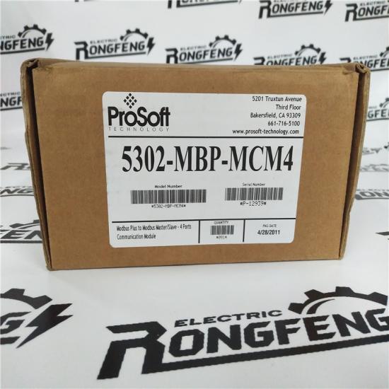
Xiamen Rongfeng Electrical Equipment Co., Ltd. स्थित है ज़ियामेन, फ़ुज़ियान प्रांत। इसका व्यापार क्षेत्र पूर्वी चीन, दक्षिण चीन, उत्तरी चीन, दक्षिण पश्चिम चीन और दुनिया के अन्य हिस्सों को कवर करता है। मुख्य dcs नियंत्रण प्रणाली स्पेयर पार्ट्स, पीएलसी सिस्टम स्पेयर पार्ट्स और रोबोट सिस्टम स्पेयर पार्ट्स, लाभ ब्रांड: एलन ब्रैडली, बेंटली नेवादा, एबीबी, इमर्सन ओवेशन, हनीवेल डीसीएस, सीमेंस। रॉकवेल ics ट्रिपलएक्स B फॉक्सबोरो ider श्नाइडर पीएलसी uc जीई फानुक, मोटोरोला, हेसा, प्रोसॉफ्ट और अन्य आयातित औद्योगिक भागों, कंपनी हमेशा "अखंडता, दक्षता, जीत @ @! @ और नवाचार" के व्यापार दर्शन का पालन करती है, और हर नए कार्य करती है। और "गुणवत्ता आश्वासन, ईमानदार सेवा, ग्राहक पहले" के काम करने के रवैये के साथ पुराने ग्राहक, प्रतिस्पर्धी उत्पाद की कीमतों, विशाल सूची और उत्कृष्ट गुणवत्ता, तेजी से वितरण समय और पूर्व की पूरी श्रृंखला पर भरोसा करते हैं। @ बिक्री परामर्श, के बाद @ बिक्री सेवा, उच्च के साथ ग्राहकों को प्रदान करना जारी रखें। @ गुणवत्ता वाले उत्पादों, मुख्य उत्पादों का व्यापक रूप से उपयोग किया जाता है इलेक्ट्रॉनिक्स, धातु विज्ञान, रासायनिक उद्योग, बिजली संयंत्र, इस्पात संयंत्र, रबर, सीमेंट, यांत्रिक उपकरण, निर्माण और अन्य उद्योग।
मुख्य उत्पादों, बेहतर आपूर्ति और पर्याप्त स्टॉक and
सभी ब्रांड DCS, PLC स्पेयर पार्ट्स:
1 Invensys Foxboro: I / एक श्रृंखला प्रणाली, FBM (क्षेत्र इनपुट / आउटपुट मॉड्यूल) अनुक्रम नियंत्रण, ट्रेपोज़ाइडल लॉजिक कंट्रोल, दुर्घटना रिकॉल प्रोसेसिंग, डीएसी, इनपुट / आउटपुट सिग्नल प्रोसेसिंग, डेटा संचार और प्रसंस्करण।
2 und Invensys Triconex: redundant गलती - सहनशील नियंत्रण प्रणाली, सबसे आधुनिक ...। @ ट्रिपल मॉड्यूलर अतिरेक (TMR) संरचना पर आधारित सहिष्णु नियंत्रक।
वेस्टिंगहाउस (वेस्टिंगहाउस): ओवेशन सिस्टम, डब्ल्यूडीपीएफ सिस्टम, मैक्स 1000 सिस्टम स्पेयर पार्ट्स।
3: रॉकवेल एलेन - ब्रैडली: निर्भरता रयान, SLC 500 / 1747 - 1746, MicroLogix / 1761 / 1763 / 1762 / 1766 / 1766 / - 1764, CompactLogix / / 1769 / / १56६,, लॉगिक्स ५००० / १ /५६ / १ / ९ / १ ९ ४ / / १ 17६० / १ ६, पीएलसी - ५ / १ १ / / १, ,५, आदि
4 series श्नाइडर मोडिकॉन: क्वांटम 140 श्रृंखला प्रोसेसर, नियंत्रण कार्ड, पावर मॉड्यूल, आदि।
5 C ABB: औद्योगिक रोबोट स्पेयर पार्ट्स DSQC श्रृंखला (नंबर 2, नंबर 3, नंबर 4, नंबर 3, नंबर 4, नंबर S4C, IRC5), बेली INFI 90, आदि:
6 si सीमेंस (सीमेंस): सीमेंस मूर, सीमेन्स सीमैटिक सी 1, सीमेंस सीएनसी सिस्टम इत्यादि।
7 MV मोटोरोला (Motorola): MVME 162, MVME 167, MVME1772, MVME177 और अन्य श्रृंखला।
XYCOM: I / O, VME बोर्ड और प्रोसेसर।
8) जीई FANUC (जीई FANUC): मॉड्यूल, कार्ड, ड्राइव और अन्य स्पेयर पार्ट्स।
9 serv यास्कावा (ओचुआन): सर्वो नियंत्रक, सर्वो मोटर, सर्वो चालक ।:
10 x बॉश रेक्स्रोथ (बॉश रेक्स्रोथ): इंद्रमट, I / O मॉड्यूल, PLC नियंत्रक, ड्राइव मॉड्यूल और इतने पर।
11 valve वुडवर्ड (वुडवर्ड): एसपीसी वाल्व स्थिति नियंत्रक, PEAK150 डिजिटल नियंत्रक।
औद्योगिक रोबोट प्रणाली के लिए स्पेयर पार्ट्स
लाभ ब्रांड: abb रोबोट, FANUC रोबोट, YASKAWA रोबोट, KUKA रोबोट, मित्सुबिशी रोबोट, otc रोबोट, पैनासोनिक रोबोट, MOTOMAN रोबोट, आदि। यदि आप की जरूरत है, हम अपने दोष भाग या विनिमय को हल कर सकते हैं। पूछताछ करने के लिए आपका स्वागत है! हम आपको सबसे अच्छी सेवा देंगे!


 IPv6 नेटवर्क समर्थित